3D EM simulation is a must in the design of high-frequency CMOS circuits
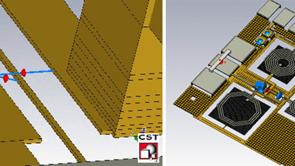
Fig. 1: Multiplier circuit (left) with different passive elements and ports replacing the active elements, ports and metal stack are emphasized on the right side.
Due to the rapid advances in the miniaturization of semiconductor processes (according to Moore’s law), high-end CMOS circuits can be used today in a frequency range far beyond 10 GHz. In contrary to low-frequency and digital circuits, their functionality is no longer defined primarily by the active elements, i.e., the transistors, but the passive elements such as inductors, capacitors and transmission lines take significant influence. Hence the electrical behavior of these elements must be included already in the basic design steps.
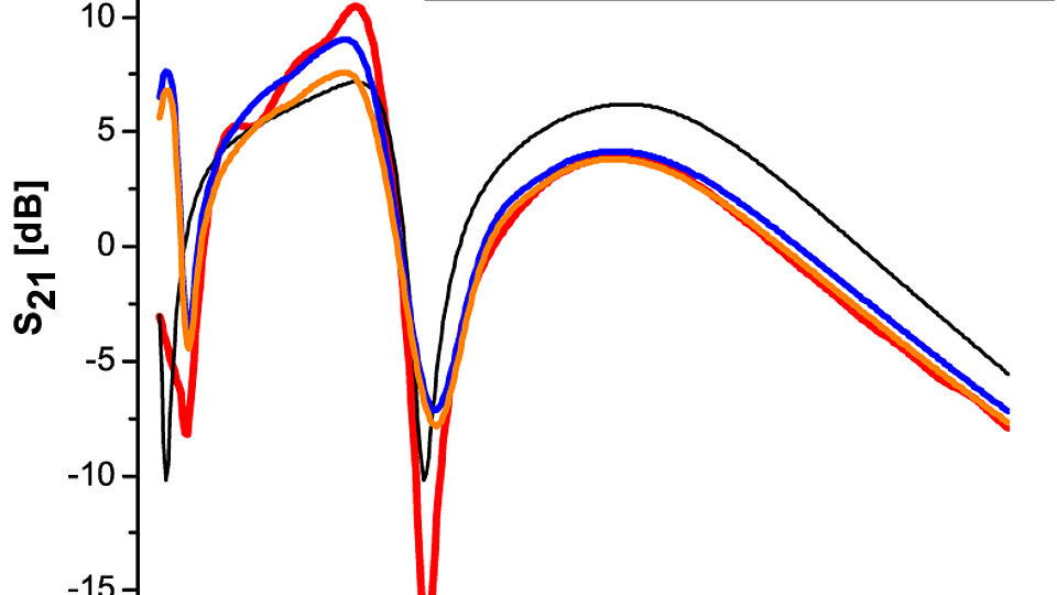
The CMOS processes realize the passive elements through a stack of metal layers separated by dielectrics on top of the semiconductor substrate with the active elements. During circuit design, it is important to use accurate models for the passive structures in the circuit simulator (eg. SpectreRF). It is also indispensable to check the circuit functions in a final step in this way. In this case, a simulation of the entire circuit must be carried out using 3D EM simulation. Active elements are not considered in the EM simulation and are replaced by internal ports. In a later step, the designer implements both the EM simulated data and the properties of the active elements in the circuit simulator in order to obtain an accurate description of the circuit. An example of such a circuit is the multiplier shown in fig. 1.The large ratios of cell sizes and the high number of cells is a challenging task for the simulation, resulting in a mesh with typical 25 million cells. Fig. 2 shows measurement data together with simulation results of the standard models, as provided by the foundry, as well as the results of the in-house EM simulation. As one can see, the results of the standard models deviate considerably from the measurements and using 3D EM simulation leads to a significantly better fit with the measured data.
FBH research: 13.01.2012

